WindSim 11.0
The Actuator Disc and Blockage Model add-on in WindSim 11 Provides You a Remarkable Method for Simulating Speed Reduction in Both Upstream and Downstream.
- New validated AD model
- Automatic grid refinement
- Visualization of two-dimensional speed reduction field
- Speed dependent inclusion of the blockage effect
- Full compatibility with all available WindSim models
- AEP calculation
- Wake Loss Calculation with the AD Model
- Wake Loss Calculation with analytical Models
- Bias of a Wakes-Only approach is provided
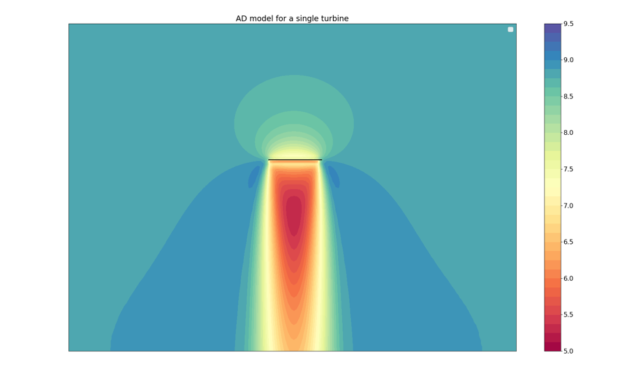
Actuator Disc Model
The presence of wind turbines can influence the wind field in several ways. The application of analytical wake models in the post process is one attempt to partially account for the wind field-turbine interactions that are not covered by the CFD calculation. A more fundamental approach is to involve the turbines into the CFD calculation beforehand so that wind field-turbine interactions can be included in the solution procedure. This approach is realized by WindSim’s Actuator Disc (AD) Model, where a turbine is represented in terms of a two-dimensional disc applying thrust forces to the wind field.
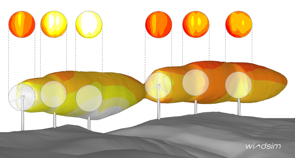
The turbulent kinetic energy is shown as an iso-surface where the colour indicates the 2D wind speed, a cross-section is depicted above representing the actuator disc area.
In the Disc Area, the resistance to the wind field modeled by these thrust forces is dynamically included in the CFD calculation. Therefore the turbine is modeled as a “real obstacle” in the wind field and resulting effects as wake effects and other wind field-turbine interactions are intrinsically contained in the CFD solution.
The AD model can be easily activated in the Terrain module with a corresponding objects file (.ows), WindSim then automatically include actuator discs at the turbine locations for all further calculations. After a velocity-dependent inclusion of the blockage effect, the outcome is summarized in the Energy module.
What’s new?
a. Validation
The actuator disc as well as the influence of the blockage effect have been tested for a lot of demo cases in order to connect the underlying technique with the variety of models and application possibilities provided by WindSim. The implemented windfarm blocking was not only tested systematically against these test cases but also against real wind farm data. Here it turned out that the implemented procedure is even suitable to reproduce rather small effects.
b. All Directions Enabled
Since the Actuator Disc is represented as a staircase in the orthogonal grid for non-orthogonal wind directions the numerical conditions for different wind directions are not precisely the same. In the actuator disc implementation of WindSim 11 the applied thrust forces, therefore, follow a new weighting scheme in order to improve directional independence.
c. Blockage Effect Model
Apart from the wake losses and the intrinsically included wake interactions, with the AD model, it is also possible to reproduce wind speed losses in front of the turbine. This is especially important when the speed losses in front of the turbines collectively form an area with reduced wind speed. This area is therefore blocked by the existence of the turbines and generally less wind speed is available.
Blockage Effect
CFD calculations clearly show the impact of the presence of a turbine in the wind field. This impact can not only be detected downstream but also upstream where a reduction of the wind speed in front of the turbine is the resulting effect. For more than one turbine this effect can become collective and appear as blocking of the whole windfarm area. This loss of wind speed is not available for energy production and consequently leads to the same rate of loss in annual energy production (AEP) that can typically range between 0% and 5%. To avoid a systematic overprediction of the AEP the consideration of the blockage effect is required.
In contrast, a speed-up region lateral to the turbine position and especially in between turbines can lead to an increase in wind speeds. This effect is naturally contained in the AD model as well and can even be included in the blockage effect calculation of WindSim (see the manual for more information). To include this effect into the wind resource assessment, WindSim provides a Blockage Model which is based on the described AD implementation.
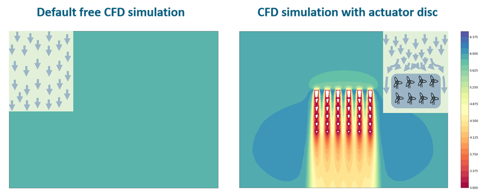
The figure shows the absolute value of the two dimensional wind speed at hub height for a CFD calculation on flat Terrain. On the left hand side no turbines in terms of AD’s are included, on the right hand side a very dense windfarm with 6×6 turbines is modeled with the AD. Except for the wake effects, the reduced wind speed bubble in front of the turbines as well as an area of speed up lateral to the windfarm, can be observed. These effects can be simply explained by the imagination of a windfarm as a blocked area as shown by the sketch in the upper right corner.
The basis of the blockage effect calculation within WindSim is given by the comparison between a calculation with and without AD. With the implemented calculation procedure it is still possible to run all common features of WindSim in connection with a Blockage Effect estimation. After a velocity dependent inclusion of the blockage effect, the outcome is summarized on the level of the Wind Resources and the Energy module in WindSim 11.
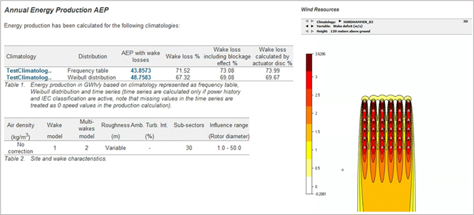
Here WindSim provides the estimation of wake losses by the AD model as well as via all analytical wake models available in WindSim. Apart from the specification of wake and blockage losses WindSim 11 provides the bias of an wakes-only approach which ensures full model control. For more information we refer to the description of the Add-on module available in the WindSim software.
Meso- Micro Coupling
Today’s mesoscale meteorological models are richer and deliver data in higher resolution than ever before. WindSim will help you leverage these advances.
WindSim provides you with different tools depending on the type of mesoscale datasets available and the needs of your project.
Point-like Mesoscale Data Assimilation
In WindSim 11 you can assimilate mesoscale wind data as a climatological input. This allows you to conduct site assessments without the need of meteorological masts, while including the long-term wind conditions.
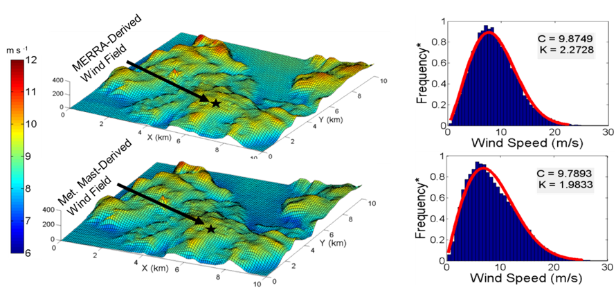
Comparison of the calculated wind resource map and wind speed distribution obtained by utilizing MERRA data (top panels) and onsite measurements (bottom panels)
Thanks to our CFD technology, WindSim is suitable to find the high wind locations produced by complex orography.
Features:
- Better detection of high wind spots than most screening tools
- Measurement-free wind resource assessment
- Inclusion of long-term wind conditions
Physical Mesoscale Downscaling
WindSim 11 allows you to physically downscale mesoscale 3-D wind fields. It derives the local wind conditions from the mesoscale (like atmospheric stability, wind shear and wind veer) and enhance them with our CFD technology.
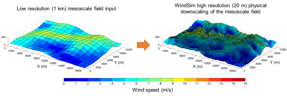
Comparison of the wind field simulated by a mesoscale model (left) and by WindSim using nesting to the same mesoscale field
The new user interface included in WindSim 11 facilitates the data pre-processing for conducting WindSim simulations coupled with mesoscale models. We also provide you with WindSim’s unique procedures to aggregate the downscaled mesoscale fields per wind direction for AEP calculations.
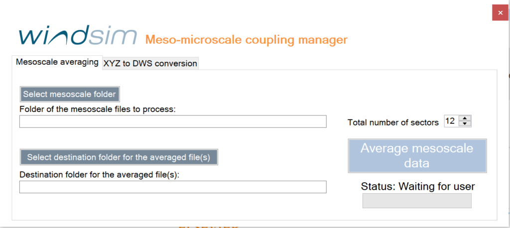
Meso-microscale coupling user interface in WindSim 11. This console takes 3D mesoscale datasets as inputs and provides you with boundary conditions for your WindSim simulations.
Physical mesoscale downscaling delivers you the following advantages:
- Simulation of realistic atmospheric flow conditions
- Consideration of atmospheric stratification in 3-D
- Simulation of mesoscale phenomena like low-level jets and wind turning
- Procedure to calculate AEP
- Applicable without onsite measurements
Additional features:
- Support for the Weather Research and Forecasting (WRF) and other meteorological models
- Applicable for forecasting
- User friendly interface
For further technical information, we invite you to check our published scientific article here.
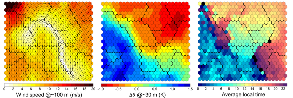
WindSim has developed a sophisticated weather classification tool based on machine learning. In a fully automated manner, you can obtain the most predominant weather patterns occurring at your site. These patterns can be then downscaled using WindSim’s meso-microscale coupling technology. This approach is especially advantageous for sites with marked diurnal cycles and unidirectional wind.
Meso-microscale coupling user interface in WindSim 11. This console takes 3D mesoscale datasets as inputs and provides you with boundary conditions for your WindSim simulations.
WindSim currently provide the consulting service for wind resource assessment and screening utilizing this advanced meso microscale coupling approach.
Features:
- Procedure to calculate AEP
- Advantageous for sites marked diurnal cycles and unidirectional wind
- Wind resource assessment and AEP estimations based on the predominant weather patterns
- Applicable without onsite measurements
- Fully automated obtention of the main wind conditions at your site
- Detection of main stability conditions